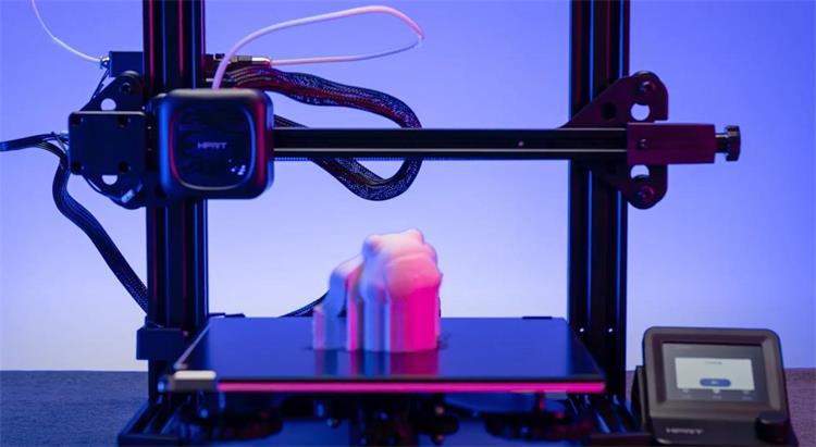
Build around a documented design
Start a DIY FDM printer with a documented mechanical design and compatible bill of materials. A collection of individually good parts is not necessarily a working machine: mounting geometry, voltages, sensor types, heater loads, firmware support, and cable routing must agree.
Define the build volume, materials, available space, and maintenance budget before buying parts. Keep the design’s assembly manual and wiring diagram beside this checklist. This guide explains the sequence and decisions; it does not replace the electrical specifications for your hardware.
Match the major components
| Subsystem | Check before assembly |
|---|---|
| Frame | Squareness, rigidity, mounting dimensions and access |
| Motion | Kinematics, rail alignment, pulleys, belts and motor drivers |
| Toolhead | Hotend limits, extruder gearing, cooling and sensor compatibility |
| Electronics | Pin assignments, heater ratings, driver settings and connectors |
| Power | Supply voltage, total load, protection, grounding and wire ratings |
| Build surface | Mounting, usable area, operating temperature and probe behavior |
Frame
Assemble on a flat reference surface, check diagonals, and tighten the frame in the design’s specified order. A twisted frame can make motion bind even when the bed mesh looks plausible.
Motion system
Align rails or rods before tightening their mounts. Check smooth travel without forcing a carriage through a tight spot. Set belt tension using the design’s method; a universal force value is not appropriate for every belt width, span, or frame.
Extruder and hotend
Match filament diameter, extruder gearing, heater cartridge, thermistor, and cooling to the intended materials. Follow the hotend manufacturer’s nozzle assembly and tightening procedure. A loose hotend joint can leak even when extrusion calibration is correct.
Control board
Use the exact board revision’s pinout. Record stepper driver type, sense resistor or current configuration, and probe wiring. Similar-looking connectors are not proof of matching pin order or voltage.
Power supply
Calculate the expected load and use components rated for the design. A fixed wattage recommendation cannot cover every heated bed and hotend combination. Mains wiring, earthing, fusing, strain relief, and covered terminals require the applicable hardware instructions and a qualified person where needed.
Display and host
Check whether the selected display works with the board and firmware. A Klipper host also needs reliable power and connectivity. Keep physical access to a way to stop the machine even when a web interface is available.
Assemble in stages
- Square the frame and align the motion system.
- Mount the bed and toolhead, then check travel and cable clearance by hand where the design permits.
- With power disconnected, wire from the exact board diagram and inspect every connection.
- Load firmware configured for the actual board, kinematics, heaters, sensors, and limits.
- Check readings and inputs before commanding motion or heat.
Do not proceed through a failed check. Reversing a homing direction in software can be correct, but it cannot compensate for an incorrectly wired sensor.
Calibrate the fundamentals first
Bed tramming and Z offset
Check the mechanical bed alignment, then calibrate probe offsets and mesh compensation using your firmware’s procedure. Z offset determines the nozzle gap; a mesh describes spatial variation. See the Bilinear and UBL guide for the Marlin distinction.
Axis movement
Verify movement direction, limits, homing inputs, and commanded travel before printing. Derive motion settings from the pulley, leadscrew, gearing, and microstepping. Do not change axis steps merely to force one printed cube to an exact size; extrusion and material shrinkage can affect that measurement.
Klipper calls its core distance setting rotation_distance; its rotation distance guide explains the relationship to the mechanism and the separate extruder measurement procedure.
Extrusion
Use the documented extruder calibration method at an appropriate temperature and feed rate. Check for slipping, a partial blockage, and spool drag before changing the calibration value. Tune the slicer’s material flow after the extruder’s mechanical configuration is correct.
Temperature control
Confirm that room-temperature readings are plausible and that heating the intended component raises the corresponding sensor reading. Use the firmware’s heater calibration procedure for the configured hardware. Keep thermal protection enabled and investigate faults rather than increasing limits to silence them.
Configure firmware for this machine
With Marlin, begin from a matching configuration and review the board, kinematics, sensors, heater limits, endstops, probe, and thermal protection settings. See Configuring Marlin.
With Klipper, follow its configuration checks before normal operation. Verify temperature readings, endstops, stepper direction, and homing in the documented order. Keep a dated copy of a known working configuration before tuning.
Maintain the machine and filament
Inspect fasteners, belts, cable bends, fans, and build-surface cleanliness regularly. Use the specified lubricant on the parts that require it; avoid spraying lubricant near belts and the print surface. Store filament according to the material supplier’s guidance and diagnose moisture when extrusion becomes inconsistent.
Diagnose poor layer adhesion
Separate first-layer adhesion from bonding between later layers. Check surface cleanliness and nozzle gap for the first layer. For upper layers, inspect material condition, temperature, cooling, flow, and speed. Change one parameter at a time and keep the test geometry consistent.
Tune motion after reliable basic prints
Input shaping addresses motion resonances, not loose screws or a misaligned rail. Establish mechanical condition and sensible acceleration before following the firmware’s measurement and tuning procedure. Klipper documents the process in Resonance Compensation.
Pressure advance and Linear Advance
Klipper pressure advance and Marlin Linear Advance address extrusion response during speed changes. Use the method for your firmware and tune with the intended filament and extrusion system. They are related approaches, not two independent calibrations that every machine should stack together.
Recheck the bed mesh
Repeat the first-layer test after changing the nozzle, build plate, probe mount, or mechanical alignment. Verify the mesh used by the start sequence; a saved mesh is useful only if it is loaded, active, and still representative.
Match the material to the machine
PLA, PETG, ABS, and TPU need different temperatures, cooling, adhesion, and feeding conditions. Use the supplier’s profile as a starting point, respect the hotend and bed limits, and provide ventilation appropriate to the material and location. An enclosure changes the thermal environment for electronics as well as the print.
Flexible filament also tests the extruder’s filament path. Material names alone do not determine whether a specific toolhead can feed a spool reliably.
Stop and investigate abnormal behavior
Unexpected heating, a temperature fault, smoke, damaged insulation, or a large hotend leak calls for stopping the machine and isolating power when safe. Do not continue a print to see whether the fault disappears. Let hot parts cool before inspection and follow local emergency guidance if there is smoke or fire.
Make maintenance traceable
Keep notes for motor and driver changes, rail lubrication, hotend work, firmware updates, and calibration values. Follow the hardware maker’s service procedure rather than dismantling a stepper motor or adding lubricant to it as routine maintenance.
After repairs, repeat the relevant input, motion, temperature, and first-layer checks before returning to long prints.
Define a useful completion test
A completed build homes reliably, reports sensible temperatures, heats the intended components, moves within its limits, and prints a consistent first layer before it attempts demanding models. Record the hardware, firmware configuration, material profile, and test result together. The result is more useful than an unsupported claim of microscopic precision.
References were reviewed on October 16, 2026. Hardware calibration and acceptance must be performed on the actual printer.